
Get Your Free Quote…!


This section gives a quick overview of the fundamentals of choosing and using a pump for best efficiency. This is not an exhaustive guide, but is designed to be just sufficient for non-technical personnel to get a better understanding of the technical background to this work. The following applies to most types of rotodynamic pumps.
The first step in pump selection is to determine the principal duty point, i.e. the required flow and head. The cheapest pump for the duty will probably be that which runs at the highest available speed, whilst still being able to cope with the suction conditions on site over its full operating range. However, it should be remembered that just one additional point of efficiency may be sufficient to pay for the pump over its lifetime, through savings in energy costs. Thus, a lower speed pump, if it is more efficient, may prove to be more economical in the long term. Another option which should be considered is to split the flow, i.e. to have two or more pumps running in parallel (or even, very occasionally, in series). This can also give flexibility if covering wide flow ranges. For more detail of the efficiency implications of this, see section 7.1 below.
The chosen duty of the pump should not be over-estimated. This frequently happens when allowance is made for a possible future increase in demand, and/or the system designer has been prudent and over-sized the system, and/or the purchaser has added his own ‘safety’ margin. Certainly the problem can be overcome by throttling the flow with a valve. However, deliberately restricting the system flow is far inferior to better matching of the pump to the actual system requirements in the first place. All throttling results in an unnecessary increase in energy costs, and can lead to other operational problems as explained earlier in section 4 and Fig 2.
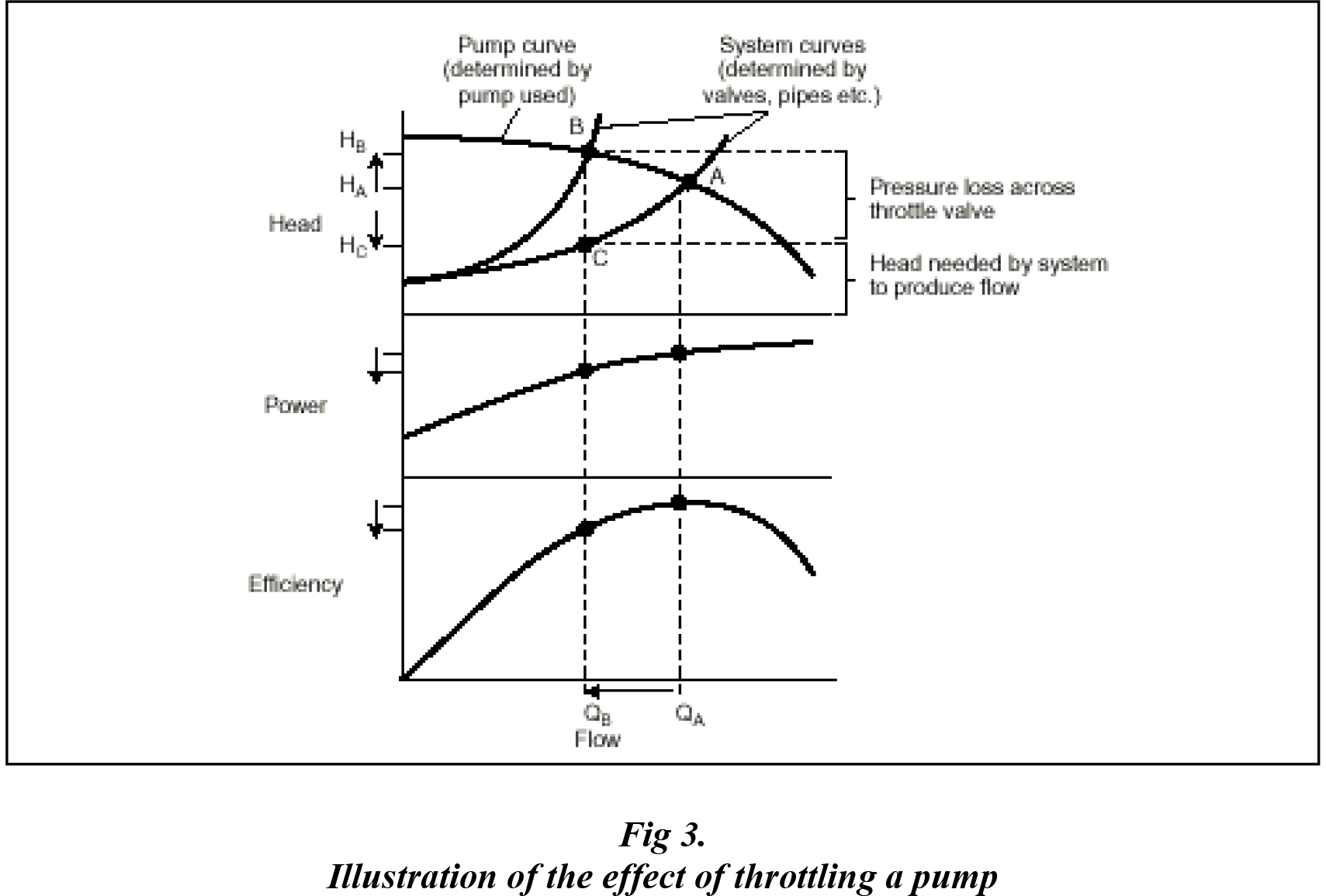
Fig 3 shows what happens if a pump is over-sized. QB represents the flow required at the chosen duty. The curve passing through points A and C is the normal system curve, i.e. the variation of head across the pump if flow increases from zero to QB, QA and beyond. The pump head/flow curve (passing through A and B) meets the normal system curve at point A, so that the pump operates at head HA delivering flow QA. Since QA is greater than the flow required (QB), the pump is over-sized.
In order to reduce the flow from QA to QB, the discharge valve must be partially closed to throttle the flow. This produces a new system curve passing through point B, so that the pump now produces the required flow QB, but is working at the higher head HB. If the pump had not been over-sized, flow QB would have been obtained by a pump head/flow curve passing through point C, so that the pump would only be working at head HC. Thus, the difference between HC and HB is purely head lost in the throttle valve, and therefore wasted energy. (For this illustration, the small variations shown in power and efficiency should be ignored.)
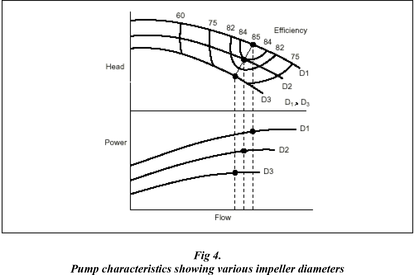
The need for throttling can be avoided by reducing the diameter of the impeller and thereby eliminating this unnecessary energy loss. Just looking at best-efficiency points (black dots), Fig 4 shows that the power absorbed by a reduced diameter impeller D2 is considerably less than that absorbed by a maximum diameter impeller D1, whilst that absorbed by the minimum diameter D3 is less again. Usually manufacturers offer the same pump casing with a range of impeller diameters because of this. Manufacturers may also offer different designs of impellers for one casing, to cope with higher or lower flows at better efficiencies than are given by the ‘standard’ impeller.
In the case of axial flow pumps, reducing the impeller diameter is not practical. In this case the pump performance can be changed by altering the angle setting of the blades. This is usually a permanent alteration but some pumps do have blades which can be reset after manufacture or even during operation.
Pumps are not usually made to standard duties. This makes comparing efficiencies less simple than with products that are made to standard duties (such as motors).
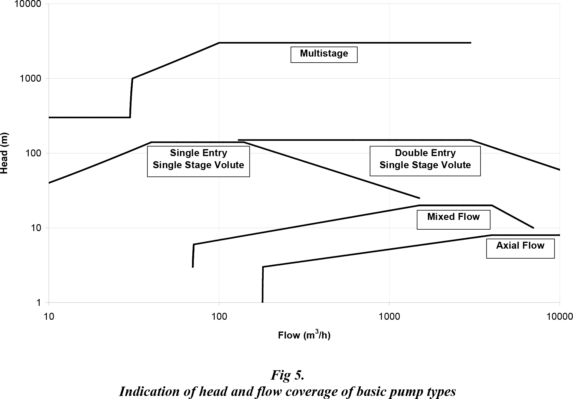
Fig 5 gives a very rough indication of the head/flow coverage of basic pump types when running at speeds of up to 3000 rev/min. (Some pump types will always run slower than this.) This plot will help when deciding which pump type is most likely to suit the chosen duty. Pumps can be provided to work beyond these ranges but will mostly be special designs.
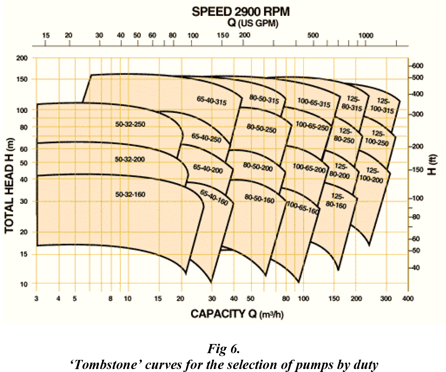
When selecting a pump from an existing range, a manufacturer will use “tombstone” curves, which show their ranges of pumps to cover a range of duties (Fig 6). The ideal duty will be towards the right of the top of a tombstone, at the point which corresponds to the BEP of the selected pump. (Each tombstone is built up from the individual pump curves such as that shown in Fig 4). However, for economic reasons manufacturers have to restrict the number of pumps that they offer. This means that even a manufacturer of particularly efficient pumps may lose out when quoting an efficiency in competition with a less efficient pump, whose BEP just happens to be nearer the requested performance. The worked example in section 6.4 below makes this clearer.
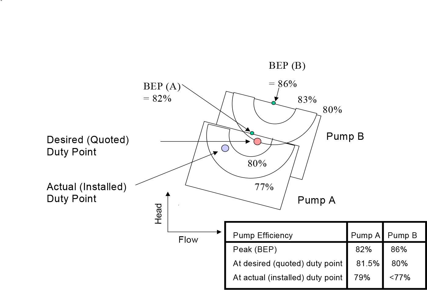
A user requests quotes for a pump at a particular desired duty. Manufacturers A and B offer the pumps shown, which are the best that they can offer from the ranges that they have. (These two pumps are excerpts from two manufacturers’ ranges of the type shown in Fig 6).
There are two important points to note:
While pump B has a higher BEP, pump A actually has a higher efficiency than pump B at the desired duty.
Over-specifying the duty means that at the actual installed duty, the efficiency of the pump will be considerably less than quoted. (In this particular case it would be better to reduce the diameter of the impeller further, to suit the installed duty without throttling, or perhaps to use a quite different pump to either of those quoted for.)
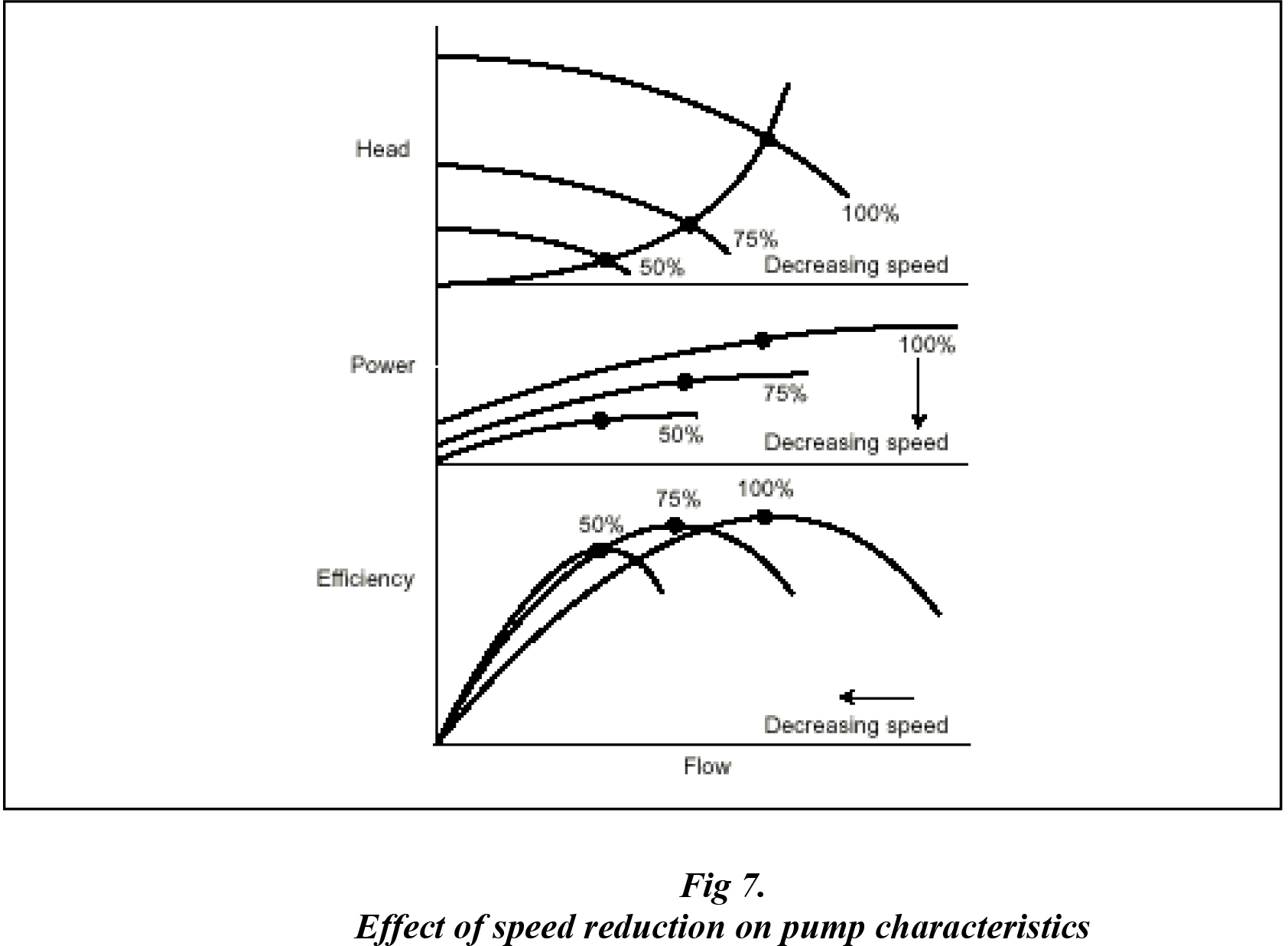
Often a manufacturer will offer the same pump at different motor speeds to allow the one pump to be used over a much wider range of duties. For instance, changing from the most common 4-pole motor to a faster 2-pole motor will enable the same pump to deliver twice as much peak flow at 4 times the head. Of course, using a relatively high speed pump will not be possible if suction conditions are not adequate. (The effect of running a pump with 4 and 2 pole motors is the same as what happens when running at 50% and 100% speeds as shown in Fig 7 below).
Variable Speed Drives allow a pump to operate efficiently over a wide range of speeds and hence duties, and so are very good for saving energy (Fig 7). They are particularly useful in systems where there is a wide variation in demanded flow.
What this all means is that the same basic pump can serve different duties depending on both the diameter and design of impeller fitted and the speed of the motor chosen. The power consumption will vary with these parameters and with other factors such as liquid specific gravity and viscosity. The size of motor required therefore needs to be determined for each application.